
Picture this: you’re in your workshop with a stack of metal sheets that need precise cuts. A traditional saw won’t touch steel, and oxy-fuel torches leave messy edges. Enter the plasma cutter—a tool that slices through metal like a hot knife through butter, creating clean cuts in seconds. But how does this seemingly magical device actually work?
Plasma cutting transforms ordinary gas into a 50,000°F jet that melts metal instantly. Understanding this process isn’t just fascinating—it’s essential for achieving professional results and extending your equipment’s life. This guide breaks down the science and mechanics behind every cut, so you can operate your plasma cutter with confidence and precision.
Plasma Cutting Fundamentals
Plasma cutters harness the fourth state of matter to slice through conductive metals. Unlike solid, liquid, or gas, plasma forms when gas molecules become so energized that electrons break free, creating a superheated, electrically conductive channel. This ionized gas becomes the cutting tool that melts through metal with surgical precision.
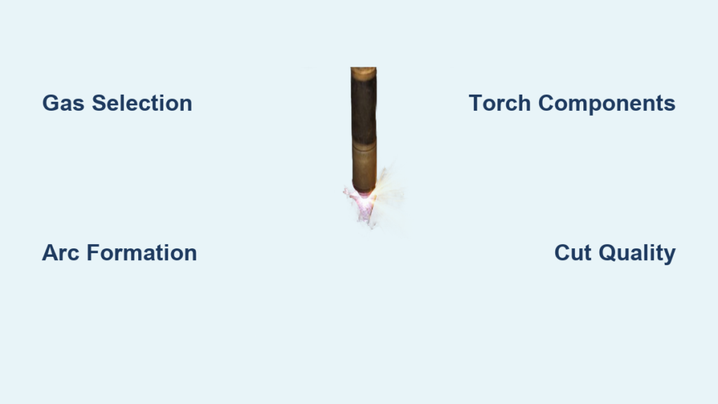
Gas Selection for Plasma Formation
The process begins with compressed gas—shop air, nitrogen, oxygen, or argon—flowing through a precisely engineered torch. Each gas offers distinct advantages:
- Compressed air: Most economical, cuts all common metals
- Nitrogen: Produces clean, oxide-free cuts on stainless and aluminum
- Oxygen: Maximizes cutting speed on carbon steel through exothermic reaction
- Argon-hydrogen: Ideal for thick aluminum and stainless applications
Your gas choice directly impacts cut quality and speed. For example, oxygen plasma increases cutting speed by 25-40% on steel through an exothermic reaction, but at the cost of faster consumable wear. When you’re deciding how does a plasma cutter work with different materials, remember that gas selection is your first critical parameter.
Temperature Transformation Process
As the electric arc forms, gas temperatures skyrocket from room temperature to 20,000-50,000°F in milliseconds. This extreme heat transforms the gas stream into plasma—a mixture of free electrons, positive ions, and neutral atoms capable of conducting electricity and melting any metal it contacts. The plasma jet exits the torch at 20,000-30,000 feet per second, creating enough force to blow molten metal away from your cut line.
Arc Creation Sequence

Creating a plasma arc follows a precise sequence that happens in fractions of a second. Understanding this sequence helps troubleshoot cutting issues and optimize performance when you’re learning how does a plasma cutter work in practice.
Pilot Arc Formation
The cutting cycle initiates with a pilot arc between the electrode (negative) and nozzle (positive). This small arc—generated by 5,000-10,000 volts at 2-5 MHz frequency—ionizes the gas flow within the torch body, creating the conductive path needed for main arc transfer. Modern systems use contact start or blowback technology instead of high-frequency interference, making them safer and more compatible with sensitive electronics.
Main Arc Transfer
When the pilot arc contacts your grounded workpiece, the power supply detects this connection and switches from pilot mode to cutting mode. The main cutting arc transfers instantly from the electrode to your metal, establishing the continuous plasma column that performs the actual cutting. This transfer happens so quickly (within milliseconds) that you’ll only notice a brief change in the arc’s appearance and sound.
Arc Stabilization Factors
Several factors maintain arc stability during cutting:
- Gas flow rate: 2-10 CFM depending on material thickness
- Torch standoff: 0.060″ to 0.375″ from work surface
- Current consistency: Stable DC power prevents arc wandering
- Consumable condition: Clean, undamaged parts ensure focused arc
When your cut quality suffers, check these factors first—they’re the most common culprits behind poor performance.
Power Supply Mechanics
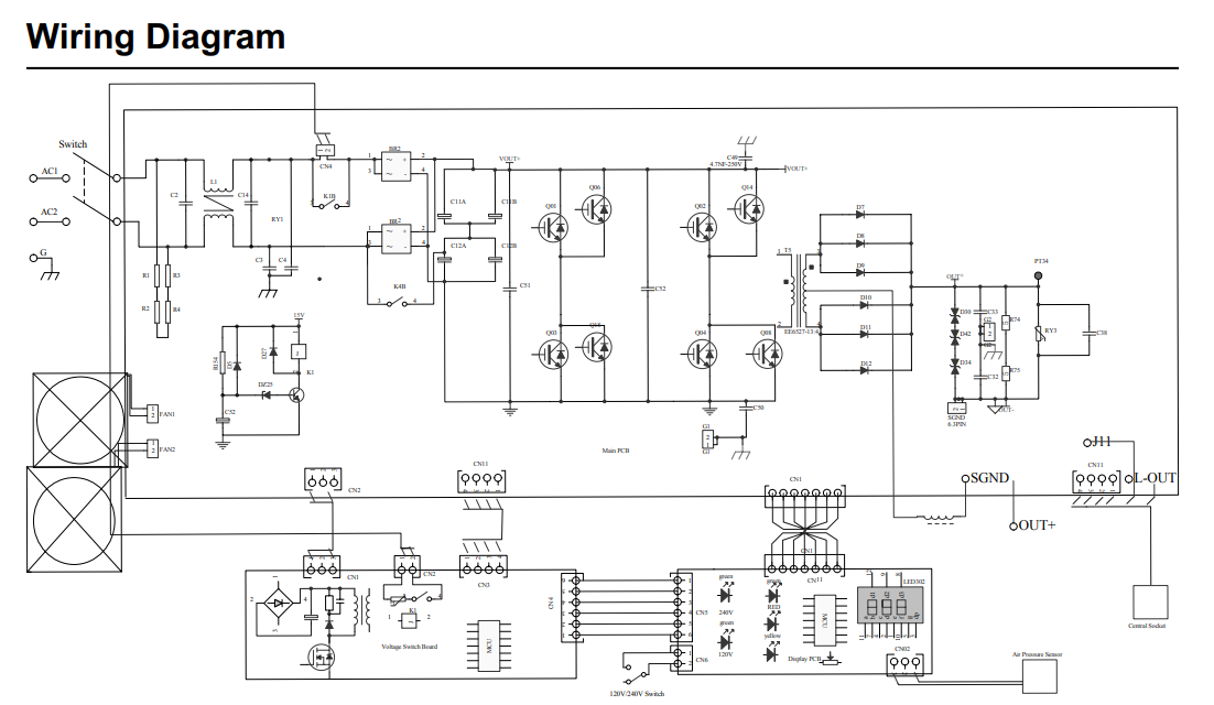
Modern plasma cutters use sophisticated electronics to convert standard AC power into precisely controlled DC cutting current. This transformation is critical to understanding how does a plasma cutter work at the electrical level.
DC Conversion Process
Your wall outlet’s 110V, 220V, or 440V AC power undergoes transformation through:
– Rectification: Converts AC to DC
– Filtering: Smoothes electrical pulses
– Inversion: High-frequency switching (10,000-100,000 Hz)
– Final rectification: Produces stable DC cutting current
Inverter technology delivers 85-90% efficiency while reducing transformer size by 75%. This advancement enables compact 60-amp units weighing under 50 pounds that once required 200-pound transformers—making plasma cutting accessible to hobbyists and small shops.
Voltage Requirements
Different cutting scenarios demand specific voltages:
– Open circuit: 200-400V needed for arc initiation
– Operating voltage: 50-400V during actual cutting
– Current ranges: 20-100 amps (portable units) to 1000+ amps (industrial systems)
When you press the trigger, the power supply delivers the exact voltage and current needed to maintain a stable arc—adjusting automatically as you move the torch across different thicknesses.
Torch Assembly Components
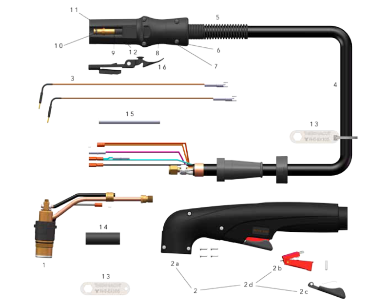
The torch assembly contains several precision components that work together to create and focus the plasma arc. Each part plays a critical role in the plasma cutting process.
Electrode Construction
The electrode serves as the electron source for the arc. Quality electrodes feature:
– Copper body: Excellent electrical and thermal conductivity
– Hafnium insert: 0.040″ to 0.250″ diameter emitter surface
– Expected life: 1-3 hours continuous cutting
– Wear indicator: Pitting depth exceeding 0.040″ signals replacement
As you use your plasma cutter, the hafnium insert gradually erodes. When the pit becomes too deep, you’ll notice decreased cut quality and increased difficulty starting the arc.
Nozzle Function
The nozzle’s precision-machined orifice (0.030″ to 0.313″ diameter) constricts the plasma arc, increasing its velocity and temperature while focusing the stream. Key specifications:
– Material: Copper or copper alloy for heat dissipation
– Orifice tolerance: ±0.001″ for consistent arc characteristics
– Life expectancy: 30 minutes to 4 hours based on cutting parameters
– Failure modes: Orifice enlargement or irregular shape
A worn nozzle creates a wider kerf and angled cuts—watch for these signs to know when replacement is needed.
Gas Flow Dynamics
A swirl ring imparts rotational motion to the gas flow, creating a vortex that:
– Stabilizes the plasma arc column
– Provides concentric cooling to consumables
– Improves cut edge perpendicularity
– Extends consumable life through even wear patterns
This swirling motion is why you’ll see a distinctive blue cone shape in a properly functioning plasma arc.
Material Removal Process
Once the plasma arc contacts your metal, two simultaneous processes remove material along the cut line. Understanding this mechanism is key to mastering how does a plasma cutter work.
Metal Melting Mechanism
The plasma arc’s extreme temperature melts metal through:
– Direct heat transfer: 50,000°F plasma contacting metal surface
– Joule heating: Electrical resistance within the material
– Exothermic reactions: Oxygen plasma creates additional heat with steel
As you move the torch, the leading edge of the cut melts while the trailing edge cools rapidly, creating that characteristic clean edge plasma is known for.
Molten Metal Ejection
High-velocity gas flow (20,000-30,000 feet per second) creates kinetic force that:
– Blows molten metal downward through the kerf
– Removes dross from the cut edge
– Provides shielding gas protection
– Cools the newly formed cut surfaces
This ejection process is why plasma cutting works best with downward motion—you’re working with gravity to remove molten material.
Cut Quality Determinants
Achieving smooth, perpendicular cuts requires balancing:
– Arc energy: Sufficient for complete penetration
– Travel speed: Fast enough to prevent excessive melting
– Standoff distance: Consistent torch height maintenance
– Gas parameters: Proper flow rate and pressure
When you notice dross forming on the bottom edge of your cut, it typically means your travel speed is too slow for the material thickness.
System Types and Capabilities
Different plasma cutting systems serve various applications, from light fabrication to heavy industrial use. Selecting the right system depends on your specific needs.
Conventional Systems
Standard plasma cutters operate at 30-130 amps using air or nitrogen:
– Cutting range: Materials up to 1 inch thick
– Speed capabilities: 20-500 inches per minute
– Kerf width: 0.060″ to 0.250″ typical
– Edge quality: Good for general fabrication
These systems offer the best value for most workshops, providing clean cuts on steel up to 3/4″ thick.
High-Definition Systems
Advanced systems deliver superior precision through:
– Operating current: 130-800 amps
– Kerf width: Narrow 0.040″ to 0.125″
– Angularity: ±1-3 degrees on cut edges
– Materials: All metals with appropriate gas selection
These systems are ideal for applications requiring minimal post-processing, such as precision fabrication shops.
Precision Systems
State-of-the-art machines achieve near-laser quality:
– Kerf width: Ultra-narrow 0.020″ to 0.060″
– Angularity: Within ±0.5 degrees
– Multi-gas capability: Computer-controlled gas mixing
– CNC integration: Automated parameter optimization
For critical applications where edge quality matters, these systems deliver exceptional results with minimal dross.
Safety and Maintenance Systems
Modern plasma cutters incorporate multiple safety features to protect operators and equipment. Understanding these systems is part of knowing how does a plasma cutter work safely.
Electrical Protection
Built-in safety systems include:
– GFCI protection: Prevents electrical shock
– Voltage reduction: Lowers open-circuit voltage when idle
– Double insulation: Torch body isolation
– Ground detection: Ensures proper work cable connection
These features make modern plasma cutters significantly safer than older models that used high-frequency starting.
Arc Starting Safety
Contemporary systems eliminate high-frequency interference through:
– Contact start: Low-voltage pilot arc initiation
– Blowback starting: Electrode movement creates arc
– Capacitive discharge: Controlled energy release
– Reduced EMI: Minimal electronic interference
This safety evolution means you can use plasma cutters near computers and sensitive electronics without interference.
Consumable Monitoring
Visual indicators for maintenance timing:
– Electrode pitting: Replace when depth exceeds 0.040″
– Nozzle orifice: Check for roundness and diameter
– Shield condition: Inspect for spatter or cracks
– Gas flow: Verify consistent pressure and volume
Regular consumable inspection prevents unexpected downtime and maintains consistent cut quality.
Understanding how does a plasma cutter work transforms you from a machine operator into a cutting expert. Each component—from the electrode’s hafnium insert to the swirl ring’s gas dynamics—plays a crucial role in creating that perfect cut. By mastering these principles, you’ll achieve cleaner cuts, extend consumable life, and tackle projects with confidence.
Remember: the 50,000°F plasma stream is only as good as your understanding of the system controlling it. Practice these concepts, monitor your results, and adjust parameters systematically. Your metal cutting will never be the same.