That unboxing moment when your Miller plasma cutter arrives sparks big dreams—custom brackets for your truck, flawless exhaust repairs, or intricate metal art. But without the right technique, you’ll waste money on ruined consumables and produce jagged cuts that require hours of grinding. Most beginners skip critical setup steps, leading to inconsistent arcs and dangerous dross buildup. This guide cuts through the confusion with battle-tested procedures used by professional fabricators. You’ll learn exactly how to configure your Miller unit for clean cuts on everything from delicate sheet metal to 1/2-inch steel plate—starting with the safety gear that prevents third-degree burns from molten metal splatter.
Essential Safety Gear Requirements
Eye and Face Protection
Ignoring proper eye protection risks permanent vision damage from plasma cutting’s intense UV radiation. For cuts under 40 amps, wear ANSI Z87.1-approved shade #5-#8 safety glasses with side shields. When cutting thicker materials at 50+ amps, immediately switch to a shade #9-#13 auto-darkening helmet. Never rely on standard welding goggles—they won’t block the plasma arc’s unique spectrum. Position a full-face shield over your helmet during overhead cutting to deflect sparks that bypass eye protection.
Complete PPE Checklist
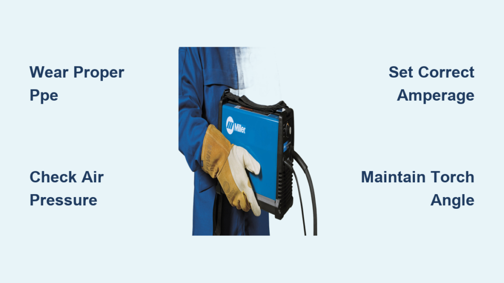
- Gloves: Heavy-duty leather welding gloves with 14-inch cuffs (like Miller’s Weldcraft model) rated for 350°C exposure
- Clothing: Flame-resistant (FR) cotton coveralls—no synthetics that melt onto skin. Add a leather apron for overhead work
- Respirator: P100 cartridge respirator mandatory when cutting galvanized steel to avoid zinc fume fever
- Footwear: EH-rated steel-toe boots with oil-resistant soles to prevent slips on metal shavings
- Hearing: Earmuffs rated NRR 25+ since plasma cutters operate at 115 dB
Workspace Safety Setup
Eliminate fire hazards by removing all flammables within 35 feet of your cutting zone. Position a 10-lb Class C fire extinguisher within arm’s reach—not across the shop. Verify your workspace has 2,000 CFM ventilation per 1,000 sq ft; open garage doors aren’t sufficient for indoor cutting. Test GFCI outlets with a circuit tester before connecting the plasma cutter—moisture near electrical components causes fatal shocks.
Machine Setup and Power Connection
Voltage and Power Requirements
Connect 110V Miller units (like the Spectrum 375) to a dedicated 20-amp circuit—never share with compressors or grinders. For 220V models (Spectrum 875X), use a 50-amp circuit with NEMA 6-50 receptacle. Industrial three-phase units require professional electrical installation. Always check your machine’s amperage rating against material thickness: a 40-amp cutter handles up to 3/8-inch steel, while 80-amp units slice through 1/2-inch plate.
Compressed Air System
Attach your air compressor using 3/8-inch ID hose rated for 150 PSI. Install a coalescing filter/water separator within 20 feet of the plasma cutter and set regulator output to 65 PSI for 40-amp machines (60 PSI for 30-amp units). Test for leaks by spraying soapy water on connections—bubbles indicate pressure loss that causes unstable arcs. Drain your compressor tank daily to prevent moisture from contaminating the plasma stream.
Torch Assembly Sequence

1. Insert electrode until it clicks into place—force causes misalignment
2. Install swirl ring with gas holes facing the electrode (not the nozzle)
3. Fit nozzle ensuring 1/16-inch gap between electrode tip and orifice
4. Secure retaining cap hand-tight plus 1/4 turn—overtightening cracks ceramic parts
5. Add shield cup for drag cutting on thin materials
Route cables with 8-inch minimum bend radius and secure every 3 feet. Kinked hoses cause air pressure drops that ruin cut quality.
Cutting Settings by Material Thickness

Thickness and Speed Chart
| Material Thickness | Amps | Travel Speed (IPM) | Technique |
|---|---|---|---|
| 22-18 gauge | 15-20 | 15-20 | Drag cutting |
| 1/8-inch | 25-30 | 8-12 | 1/8″ standoff |
| 3/8-inch | 55-60 | 2-3 | Edge start only |
| 1/2-inch | 60-80 | 1-2 | Severance cut |
Critical tip: Increase amperage 25% when cutting aluminum. For stainless steel, reduce amps 10% and use nitrogen gas if possible.
Arc Starting Techniques
Pilot arc start is your go-to method: Hold torch 1/8-inch above metal, press trigger, and wait for the arc to stabilize (1 second) before touching the surface. For thick plate, use edge starts—position torch at material edge rather than piercing through. Never use scratch-start technique on precision work; it damages nozzles and creates rough cut edges.
Pre-Cut Checklist and Setup
Daily Inspection Routine
Before pressing the trigger, inspect consumables: Electrodes should have smooth, rounded tips—not deep pits exceeding 1/32-inch. Nozzles must have perfectly circular orifices; oval holes cause angled cuts. Test air pressure while holding the trigger—pressure must hold steady at 65 PSI. Listen for a crisp “hiss” during pilot arc initiation; sputtering means replace consumables immediately.
Workpiece Preparation
Secure metal with magnetic clamps (not vice grips that conduct electricity). Mark cut lines with soapstone—permanent markers vaporize into toxic fumes. Plan your cut sequence to minimize stops; restarting arcs accelerates consumable wear by 40%. For internal cuts, drill a 1/4-inch starter hole to prevent slag buildup at the entry point.
Proper Cutting Techniques
Starting Your Cut
Position the torch perpendicular to the metal at your starting point. Angle it 65° toward your travel direction, press the trigger, and wait 1.5 seconds for full penetration. Rotate to 90° and begin moving at a steady pace—too slow causes excessive dross, too fast creates rough edges. For sheet metal under 1/8-inch, use drag cutting with the shield cup sliding directly on the surface.
Maintaining Cut Quality
Watch the cut edge for uniform dross: A thin, consistent line means perfect speed. Heavy slag buildup? Increase travel speed by 10%. Rough edges? Reduce speed or replace the nozzle. Listen for the arc sound—steady hissing indicates correct speed, while sputtering means you’re moving too fast. Pause 2 seconds at corners to ensure complete penetration before changing direction.
Finishing Techniques
Slow to half speed during the last inch of your cut to prevent slag “tails.” Release the trigger and let post-flow air cool consumables for 5 seconds before lifting the torch. Never stop mid-cut and restart—the double arc destroys nozzles. For cutouts, finish at the edge rather than stopping inside the workpiece.
Troubleshooting Common Problems
Fixing Poor Cut Quality
Excessive dross? Immediately check air pressure—low PSI is the #1 cause. If pressure is correct, increase travel speed 15% or replace worn nozzles. Angled cuts indicate torch angle errors; maintain 90° perpendicular to the surface. Rough edges signal incorrect amperage—verify settings against your material thickness chart.
Solving Arc Starting Failures
When the arc won’t ignite: First replace the electrode (pit depth >1/32-inch is failure point). Verify ground clamp connects to bare metal—not painted surfaces. Test air pressure at the torch tip; below 60 PSI prevents arc transfer. If problems persist, check for kinked air hoses restricting flow.
Maintenance and Consumable Care
Daily Maintenance Tasks
- Inspect electrodes for deep pits after every 30 minutes of cutting
- Clean air filters with compressed air (replace when clogged)
- Tighten ground clamp connections to prevent voltage drops
- Drain air compressor tank and inline filters before shutdown
- Blow torch head with 30 PSI air to remove metal spatter
Consumable Replacement Guide
Electrodes fail when pit depth exceeds 1/32-inch or starting becomes inconsistent. Nozzles need replacement when orifices enlarge by 10%—measure with calipers. Swirl rings last longest but clog with debris; replace when gas flow becomes uneven. Always change electrodes and nozzles as matched sets—mixing old and new parts causes premature failure.
Material-Specific Settings
Stainless Steel Adjustments
Reduce amperage 10% below mild steel settings and use nitrogen plasma gas if available. Expect slight discoloration on cut edges—remove with a stainless steel brush (never carbon steel brushes). Cut at slower speeds (10-15 IPM for 1/8-inch) to minimize heat input and warping.
Aluminum Modifications
Increase amperage 25% and use argon/hydrogen mix for clean cuts. Cut from the painted side when possible to reduce dross. Expect heavy backside dross—grinding is unavoidable. Use continuous pilot arc mode to prevent arc wandering on non-ferrous metals.
Galvanized Steel Precautions
Remove zinc coating 1/2-inch back from cut lines with a grinder. Always wear a P100 respirator—zinc oxide fumes cause metal fume fever. Increase ventilation to 3,000 CFM and expect 3x more dross than mild steel. Plan extra grinding time for clean weld prep.
Shutdown and Storage Procedures
Proper Shutdown Sequence
- Release trigger and wait for post-flow air to stop (5-7 seconds)
- Power off the machine at the main switch
- Close compressor air valve
- Bleed pressure from all lines
- Coil cables with 12-inch loops to prevent kinks
- Store torch vertically in a rack until cool
Work Area Cleanup
Remove slag with a magnet sweeper—never bare hands (sharp edges cause cuts). Dispose of electrodes per local regulations; they contain hafnium. Log consumable usage to predict replacement needs. Wipe the machine exterior with a dry cloth to prevent moisture corrosion.
Mastering your Miller plasma cutter starts with respecting its power—both to transform metal and to destroy consumables when misused. Your first cut on scrap steel should take 10 minutes: 5 minutes checking air pressure and consumables, 5 minutes executing the cut. Remember the golden rule: Clean air equals clean cuts. When dross appears, adjust travel speed before touching the amperage knob. Within a week of practicing these techniques on scrap metal, you’ll slice through 1/4-inch plate with the precision of a CNC machine. That garage workshop just became your personal metal fabrication lab—now go cut something great.